In this page
Motivation
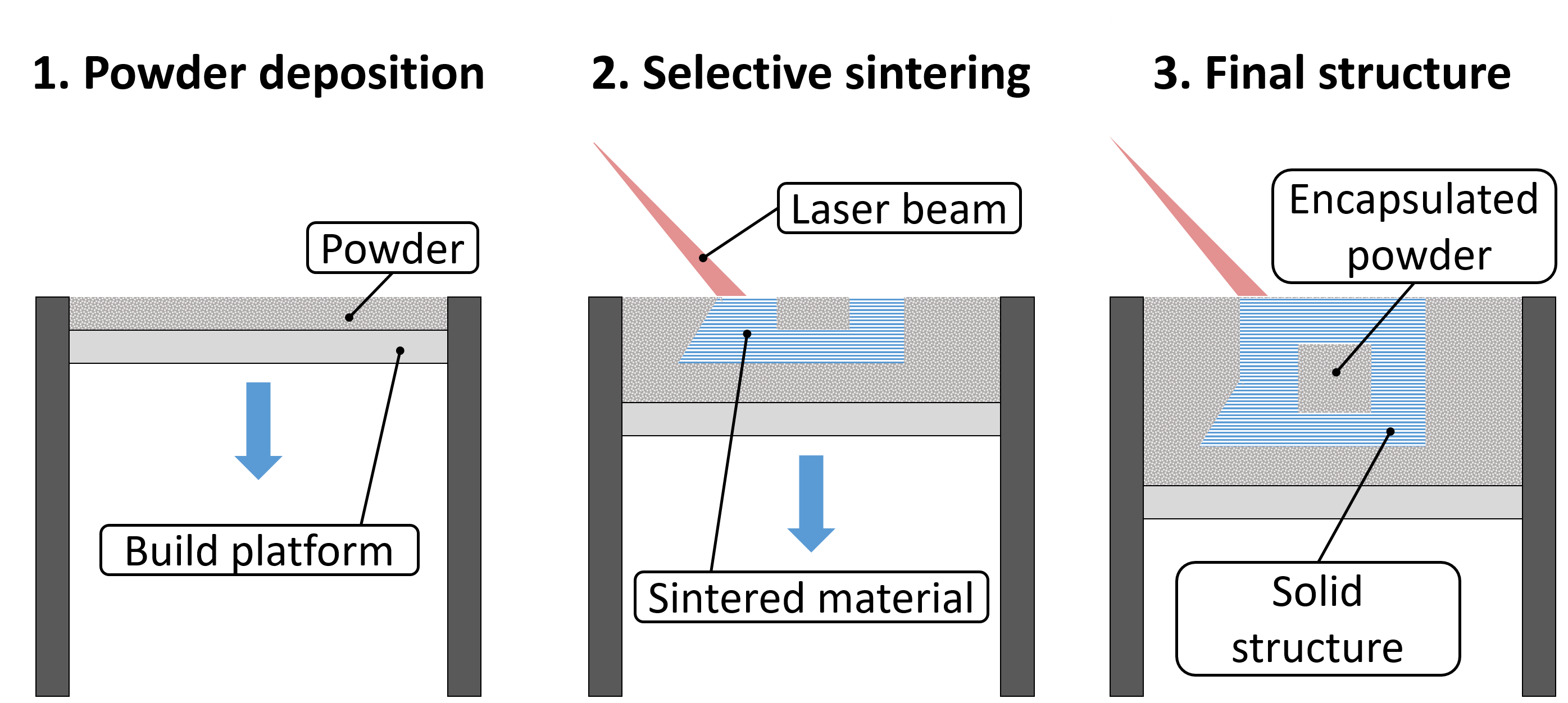
Selective laser sintering (SLS) allows for fabricating structures containing powder-filled cavities. Usually, the residual powder filling the cavities is disposed of by designing a “drainage” hole through which the cavity can be emptied. However, a cavity filled with particles is essentially a particle damper that can absorb kinetic energy and attenuate the structure’s response to external excitation. Our goal was to design and fabricate structures with embedded particle dampers to study their dynamics.
Test specimen design
Design considerations
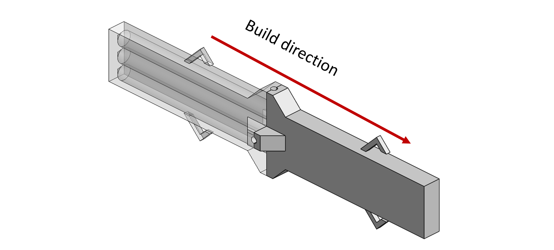
We decided to design and fabricate a beam with a rectangular cross-section, embedded with 3 cylindrical cavities along its length, inspired by Wang & Li. In SLS, the powder can support overhangs up to about 45°, so to obtain a circular cross-section of the cavities. the build direction was in the axial direction of the cavities. The cavities’ edges were designed as a cone with 45° to account for overhang support.
Fabrication process
The material available to us was Ti6Al4V (also known as Ti64). In the fabrication process of structures of Ti64 in SLS, the upper layers, which are the last to be sintered, are much hotter than the bottom layer, placed on the build platform through which heat is transferred. Due to the temperature gradient, the fabricated parts may suffer from significant residual stresses. To release these stresses, the parts usually undergo heat treatment after being removed from the printer.
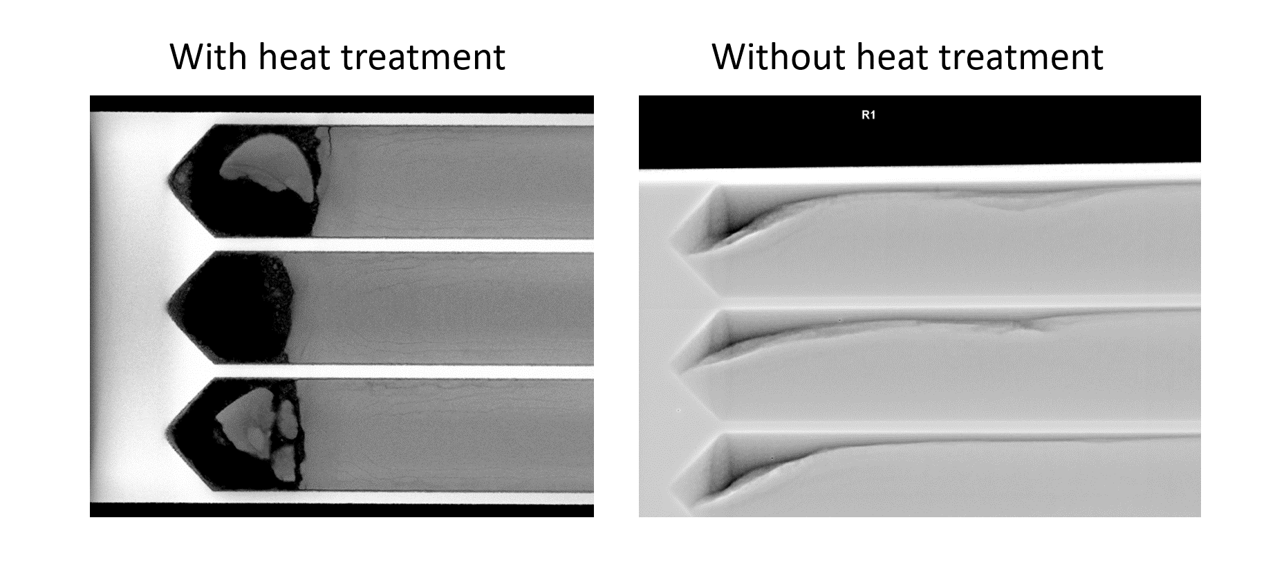
The beam we initially fabricated was heat treated according to the manufacturer’s recommendation. However, we examined the beam using an X-ray machine and found that the unsintered powder inside the cavities was “clumped” and stuck to the cavities’ sides. The clumping effect is undesired because we want the powder inside the damper to flow freely and dissipate as much energy as possible. We suspected the heat treatment of the beam to be the source of the problem, and indeed, after fabricating a beam with the same geometry, but skipping the heat treatment, we obtained a beam with freely-flowing powder.
Later when we switched to aluminum we knew to ask the manufacturer to skip the heat treatment.
Design of a reference beam
Design approach
We designed and fabricated a reference beam with no powder cavities to estimate the amount of damping added by the particle dampers to the damped beam’s structural damping. For the comparison to be valid, the natural frequency of the excited mode of the reference beam should be close to the natural frequency of the excited mode of the damped beam.
A simple estimation for the natural frequency of the damped beam is obtained under the following assumptions:
- The powder has no stiffness.
- The powder encapsulated within the cavity has the same mass as solidified material that occupies the entire volume of the cavity.
In more practical terms, the reference beam should have the following properties:
- Its cross-section’s moment of inertia (stiffness) is equal to that of the damped beam with cavities containing no material.
- Its cross-section’s area (mass) is equal to that of the damped beam if the cavities are filled with solid material.
Let us consider the damped beam and demonstrate how the reference beam was designed: The cross-section of the damped beam is shown in the image below.
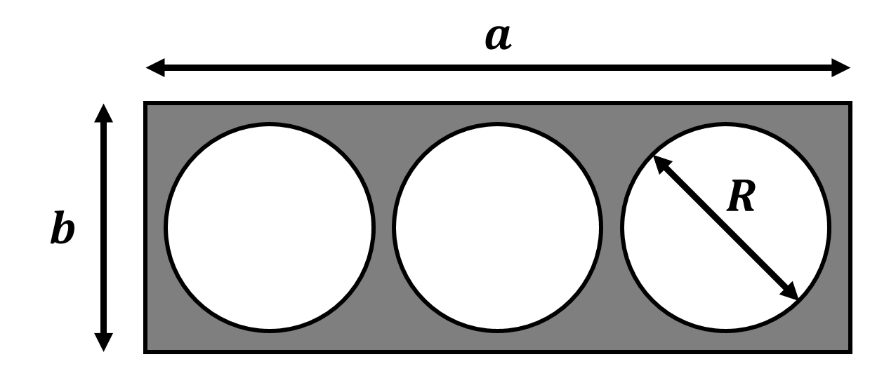
The moment of inertia of a rectangle with width \(a\) and height \(b\) about the horizontal axis: \(I_{rect}=\frac{ab^3}{12}\)
The moment of inertia of a circle with radius \(R\): \(I_{circ}=\frac{\pi R^4}{4}\)
As mentioned before, the regions with loose powder are considered empty when calculating the moment of inertia because they do not have any rigidity. Since the main axes of the circles and the rectangle coincide – the total moment of inertia of the cross-section is equal to the moment of inertia of the rectangle minus the circles’ moments of inertia, i.e.:
\(I=I_{rect}-3I_{circ}\)
The cross-section area, including the powder regions, is simply:
\(A=a\cdot b\)
Considering the reference beam’s cross-section to be a rectangle of width \(a_{ref}\) and height $b_{ref}$, the dimensions are obtained simply by:
\(\frac{1}{12}a_{ref}\cdot b_{ref}^3=I\)
\(a_{ref}\cdot b_{ref}^3=A\)
Which is solved to obtain:
\(a_{ref}=\sqrt{\frac{A^3}{12I}}\)
\(b_{ref}=\sqrt{\frac{12I}{A}}\)
Design verification
To verify this approach, the natural frequencies of the damped beam and the reference beam were estimated using finite-element analysis and compared with experiments. To account for the powder’s mass, the same assumptions were used – the powder’s mass (the mass of the “missing” material) was distributed along the sides of the cavities embedded within the damped beam.
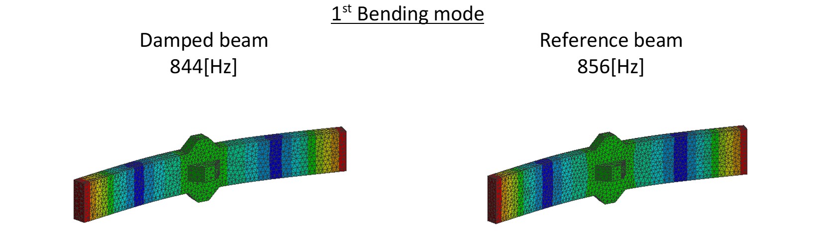
The results of the finite-element modal analysis are shown in the image below. We see a difference of less than 2% between the natural frequencies of the damped beam and of the reference beam, which can be expected.
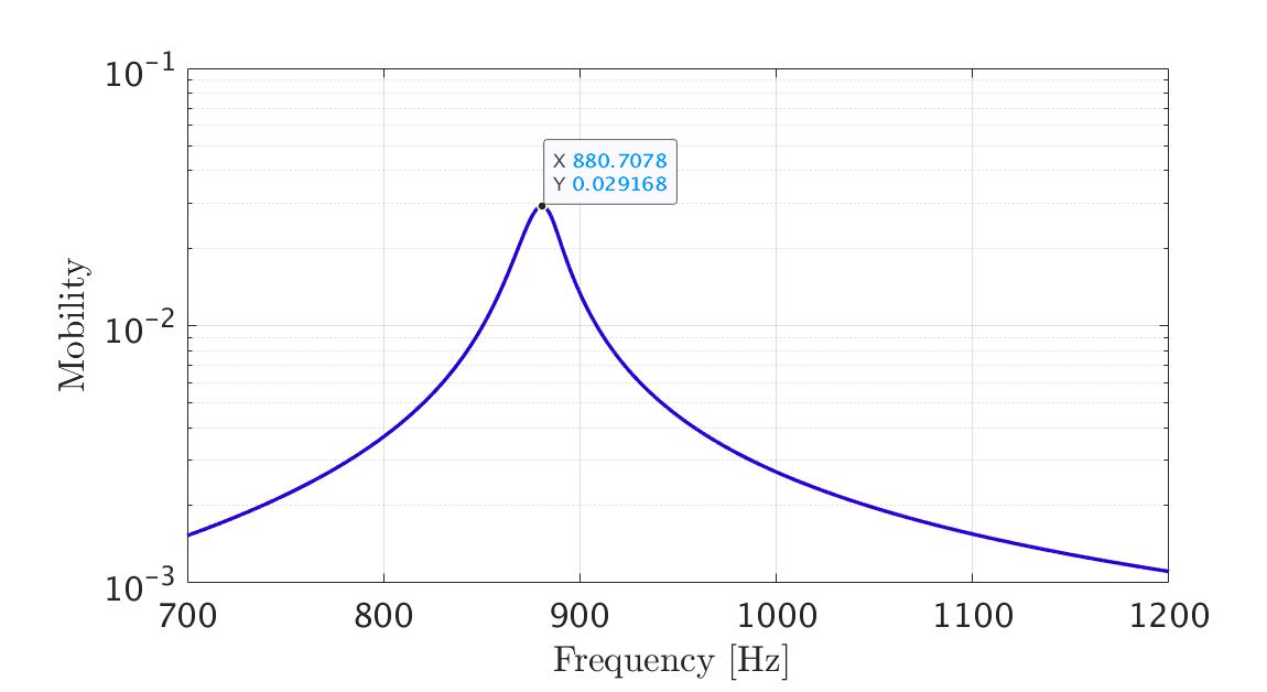
The natural frequency of the fabricated damped beam was estimated by exciting it using a swept-sine and estimating its frequency-response function. The experiment results are shown below. We see that the natural frequency obtained in the experiment is slightly higher than the one estimated using finite-element analysis.
To investigate the difference in natural frequency we examined the beam’s weight and compared it with the weight predicted by the CAD model. We found that the beam weighs about 330gr, while the CAD model predicts that the beam’s weight is about 448gr, where the solid portion weighs 210gr and the powder portion weighs 238gr (the weight of the”missing” material, assumed to fill the entire volume of the cavity with the same density as the solid material).
The difference between the finite-elements analysis and the experimental results makes sense – a lighter beam would have a higher natural frequency, but these findings have some further implications: Assuming that the mass of the solid portion is identical between the CAD model and the fabricated beam, we can calculate that the actual weight of the powder is about 120gr, about half of the expected value. This means that the filling ratio (i.e. the ratio between the volume occupied by the powder and the total volume of the cavity) obtained in the fabrication process is about 50% – an important realization for future designs.